 Categories
::: Kits :::
New Products Specials Featured Bestsellers PROJECT LEAD THE WAY 3D PRINTING Dollar Store ANTI-STATIC PRODUCTS TEACHERS CLASSPACKS Accessories Alarm-Siren-Automotive App Kits Alternative Energy AUDIO Products PLUMBING Audio Hi-Fi Application Kits Batteries Black Light Kits BLOCKS Breadboards Calculators Car Kits Cases for Kits Cold Cathode lamps Color Organ Kits Components Computer Equipment Computer Trainers Consumer Products DVD'S Educational Electronic Project-Lab Kits Engino Kits Fiber Optic kits Fluke Test Equipment Fuel Cell Kits FUSES Geiger Counters Globes Glue Guns & Accessories HVAC Hexbugs Home Application Kits Infrared-Laser Kits Interface Systems-Programmers Kits Invention Kits Laser Kits-Infrared Learn to Solder Kits LED Kits LEGO Light Application-Domestic Kits Magnifying Lamps Measuring Instrument Kits METAL KITS Microscopes DIY Soldering Kits Modules Mounted Kits-Assembled Multimeters Assembled Multimeter Kits MUSIC Non Soldering Kits Oscilloscopes OWI Robots Parallax Programming Kits Power Supplies ASSEMBLED Power Supply Kits-Charger Kits Printer Cartridges XELTEK Programmers QUIZ BOWL KITS Radio Kits Transmitters and Receivers Remote Control Unit Kits Robotic Arms - Accessories Robot Kits - Soldering Robot Kits - Non Soldering Rocket Kits Safety Products SCIENCE- Discovery Planet Science Tech and Toys SCIENCE KITS and ITEMS SCIENCE Physics/Spectrum Tubes SCIENCE- Project/Lab Kits Science Tech SCIENCE Thames & Kosmos SCIENCE Tree of Knowledge Season/Holiday Kits Security Products Software Snap Circuits Snooper Kits Solar Kits Soldering Equipment Soldering Kits in Cases Solder Sound & Light Products Strobe Light Kits Surface Mount Kits Test Equipment Assembled Test Leads Test Equipment Kits Timer & Controller Kits Tools Tool Kits/Cases Toys Trainers-Microcontollers TRAINING-OHM’S LAW UFO Kits Velleman Products Vex Robotics Video Application Kits Wire-Cable Wooden kits  Product Details
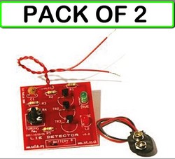
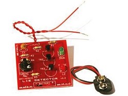
(CLONE) (2-PACK) VELLEMAN MLP106 MadLab Lie Detector DIY Electronic Kit
SKU: MLP106
Overview
LIE DETECTOR DIY KIT - solder version
Product Features:
The Lie Detector works by measuring galvanic response. In other words, when a person lies, they tend to sweat. Perspiration has a high sodium content, so sweat is conductive. Dry skin has a resistance of about 1 million ohms, whereas the resistance of moist skin is reduced by a factor of ten or more.
A person holding the probe wires will change the voltage at the upper probe wire depending on their skin resistance. The skin resistance is in parallel with R2 and, because it is likely to be similar to or smaller than R2, the voltage at the probe wire will fall as skin resistance falls.
A person holding the probe wires will change the voltage at the upper probe wire depending on their skin resistance. The skin resistance is in parallel with R2 and, because it is likely to be similar to or smaller than R2, the voltage at the probe wire will fall as skin resistance falls.
Skill Level 2. This kit requires soldering of components to the PC board while building.
- This kit requires soldering of components to the PC board while building.
- Soldering required
- Ages 13+
Product Specifications:
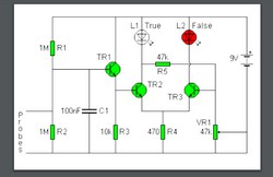
The circuit diagram of the Lie Detector is shown below. It consists of three transistors (TR1 to TR3), a capacitor (C1), two lights or LEDs (L1 & L2), five resistors (R1 to R5), and a variable resistor (VR1). Suitable transistors to use are BC547, BC548 or BC549, or any other small NPN transistor.
This circuit is based on the fact that a person's skin resistance changes when they sweat (sweating because they're lying). Dry skin has a resistance of about 1 million ohms, whereas the resistance of moist skin is reduced by a factor of ten or more.
Resistors R1 and R2 form a voltage divider. They have resistances of 1 000 000 ohms (1 mega ohms) and, because their values are equal, the voltage at the upper probe wire is half the battery voltage (about 4.5 volts).
A person holding the probe wires will change the voltage at the upper probe wire depending on their skin resistance. The skin resistance is in parallel with R2 and, because it is likely to be similar to or smaller than R2, the voltage at the probe wire will fall as skin resistance falls.
Capacitor C1 functions as a smoothing capacitor and removes the 50Hz induced mains hum that is found on a person's body.
TR1 and R3 form a buffer circuit (called an emitter-follower). The voltage at the emitter of TR1 follows the voltage at the probe wire and is now able to drive transistor TR2.
Transistors TR1 and TR2 act as a voltage comparator. If the voltage at the base of TR2 is higher than at the base of TR3 then the green LED (L1) will come on. If the reverse is true then the red LED (L2) will light.
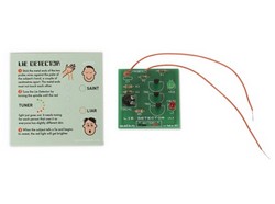
To test the Lie Detector hold the probe wires. Adjust VR1 until the green LED is just on and the red LED is just off. This is the point at which the voltage at the base of TR2 is just greater than at the base of TR3. Now use moist fingers to hold the probes. This lowers the skin resistance and causes the voltage at the base of TR2 to fall. The voltage at the base of TR3 is now greater and the red LED comes on.
Tell a Friend
Cart Contents
Order Info
TOLL FREE: 800-379-6664
INTERNATIONAL:954-574-0345
SCHOOL PURCHASE ORDERS:
FAX: 954-574-9528
INTERNATIONAL ORDERS:
MONEY ORDER,WESTERN UNION, OR BANK WIRE
(NOT INCL. CANADA)
INTERNATIONAL:954-574-0345
SCHOOL PURCHASE ORDERS:
FAX: 954-574-9528
INTERNATIONAL ORDERS:
MONEY ORDER,WESTERN UNION, OR BANK WIRE
(NOT INCL. CANADA)